

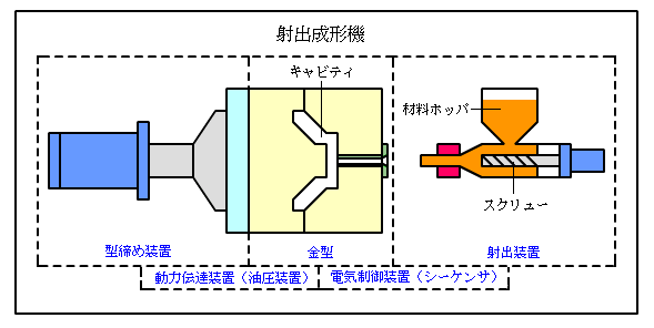
The injection molding machine consists of an injection carriage, a mold and a clamping device. This chapter explains the structure of the primary elements.
Injection Carriage
The injection carriage plastic sizes the molding material and injects it into the cavity. The most important part of the device is a screw cylinder, which makes a great difference in the molding condition. The screw within the screw cylinder is divided into 3 parts.
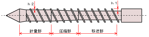
Transfer Section
This section transfers the molding material received from a material hopper into the compression section while warming up the material. It is designed to transfer the molding materials rather than mixing them. Therefore, its groove (h1) is rather deep.
Compression Section
The molding material transferred from the transfer section is mixed extensively to produce heat and melt the plastics.
The groove at the screw becomes shallower, and the pressure for compression becomes stronger as it nears the metering section. The screw at the compression section functions to force the gas and water from the molten plastics and push these back to the transfer section.
Metering Section
This section mixes the material further and produces fully plastic sized molten plastics. As the groove (h2) at the screw is shallow, the shear heat developed in this section is higher than in the compression section.
Screw Diameter and Injection Pressure
The screw diameter is related to injection pressure to a certain degree for each molding machine.
If the size of the screw changes, the ultimate injection pressure of the injection-molding machine will change.
To determine the injection pressure, the following values are used for calculation: (1) the screw diameter and hydraulic pressure, or (2) ultimate injection pressure and hydraulic pressure, or (3) the actual injection pressure calculated by the ultimate injection pressure and hydraulic pressure. Injection pressure and ultimate injection pressure are obtained as follows:
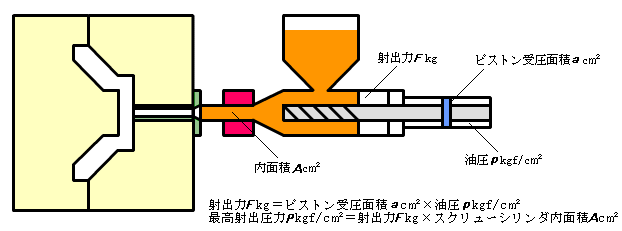
Please note that the hydraulic pressure does not indicate the actual injection pressure.
Injection Volume, Injection Load (Weight)
Molding cannot be realized if the injection volume is too small. Injection volume is not only the volume of the cavity; the volume of the runner and sprue shall also be included. The equation to obtain the injection volume is as follows:
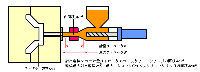
You can assume that the actual injection volume which the injection-molding machine can produce is smaller than the values indicated in the manufacturers’ catalogs.
The values in the catalogs are often the maximum injection stroke and just theoretical figures. The volume loss is not accounted for. The volume loss is the reverse flow of the molten plastics during injection.
The plasticated molten plastics with low viscosity loses a considerable amount of injection force. Molten plastics with high viscosity tends to lose less injection force.
The injection volume varies depending on the nature and the molding condition of the molding material. However, the most appropriate injection volume is said to be 60% to 70% of the maximum theoretical volume.
Injection Rate
Injection rate is the volume injected per unit time, the same meaning as the injection speed.
The shorter the injection time, the shorter the molding cycle becomes. In industrial molding, in many occasions, the quality of the part cannot be guaranteed unless it is injected with high pressures and high speeds. For example, injection molding at less than 100 tons clamping force for less than a minute is considered appropriate.
In the case of thinner molding, especially high speed is required to fill in the mold. Therefore, a high injection rate is necessary.
Elasticating Ability and Screw Speed
The injection machine performs plastination of the molding material while the product is being cooled and solidified.
The molding cycle would be wasted unless the plasticizing is completed within the cooling and solidification time. Therefore, molding injection requires large plasticizing capacity.
The volume of plastination will increase if the screw cylinder revolves more. However, this may cause a thermal decomposition to the molding material, so it is advisable not to raise the number of screw speed.
Others
When a rapid molding cycle is more important than the accuracy of the part, a machine with a higher elasticating capacity is effective.
The part with high melting viscosity should require a large operating torque for the screw. In such a case, it is better to use the screw optimized for mixing rather than plasticizing ability.
Clamping Device
The clamping device tightens the mold with great force to prevent the mold from opening and closing due to the pressure from injection. Nowadays it is generally run by hydraulic force.
There are two major systems: the direct pressure system and the toggle system:
Direct Pressure System:
It is the system in which the mold is tightened directly by the hydraulic force.
The clamping force works anywhere as long as it is within clamping stroke range.
Toggle System
This is the system using a mechanical device called a “toggle link”. Clamping force comes from mechanical power, but the force works only when the toggle arm is fully extended. Therefore, it is necessary to adjust the clamping device according to the mold thickness. The following are the comparison between the direct pressure system and the toggle system:
[Comparison Between Direct Pressure System & Toggle System]
Comparing condition |
Direct pressure system |
Toggle system |
Speed of opening/closing |
Slow |
Fast |
Mold replacement |
Easy |
Need adjustment by the thickness of the mold |
Mold clamping force |
Same force as hydraulic pressure |
More force than the given force due to mechanical tightening |
Set up of clamping force |
Easy |
Uncertain as it depends on tightening condition of bolt |
Mold opening stroke |
Small |
Large |
Calculation of the Clamping Force
Clamping force is calculated as follows: [Example] Assuming that you make two molds for the following parts (units : mm) :
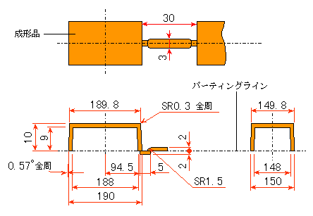
The required clamping force F [kgf] is calculated by the following equation:
| F≥A*P/0.8 |
A : Total projection area of the part [cm²] P : Average pressure within the cavity [kgf/cm²] 0.8: Safety rate
In the case of the above drawing, A becomes the projection area for the two cavities and runner parting line.
What is the total?
A = projection area of the cavities + runner portion projection
=(190*150)*2+(30*3) =57090[mm²] =570.9[cm²]
Assuming P=400 [kgf/cm²],
F ≥ 570.9*400/0.8
≥ 285450[kgf] ≥ 285.45[tf]
Therefore, a molding machine with 285.45 ton clamping force should be used.
Mold Opening and Closing Stroke
The mold opening/closing stroke needs to be examined thoroughly; otherwise, the part may not be removed from the mold.
In the toggle system, the toggle link position is moved by a thickness adjustment device, and the mold is tightened while the link is constantly extended. As such, a stroke can be secured between maximum and minimum mold thickness
In the direct pressure system, there is no structure to move the clamping device. Therefore, the stroke can be secured at the minimum thickness range. Be aware and cautious that the stroke is reduced as the mold becomes thicker.
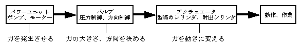
Power and Transfer System
Recently, most injection molding machines are run by the hydraulic force system. This is because the hydraulic system is easy to adjust in speed and pressure and because it can direct the force transfer freely and flexibly.
The hydraulic device consists of the following:
– Power unit, which sends oil, the source of force, into the hydraulic circuits.
– Valve which adjusts the flow and movement of the oil.
– Actuator which performs work by the force received by oil.
Electric Control
The following are 3 types of electric circuits used for injection molding:
– Power transfer circuits-control of hydraulic device
– Electric heat circuits- heater control of screw cylinder
– Power circuits-electric motor-(motor, pump) control
To control the electric circuits, no breaker point sequence (meaning continuing or in sequence) with IC is employed.
